Inverter (w/overall wiring schematic)

A forum for discussing topics relating to MacGregor Powersailor Sailboats
User avatar
bscott
Admiral
Posts: 1143
Joined: Mon Mar 08, 2004 2:45 pm
Sailboat: MacGregor 26X
Location: Arvada, Colorado 2001 X, M rotating mast, E-tec 60 with Power Thruster, "HUFF n Puff"

Inverter (w/overall wiring schematic)

Post by bscott »

I am in the process of installing a 1200 watt inverter that has a case ground post. Where is the best ground location to ground it to the :macx: :?: Wire gage :?: The primary use is to run a 600 watt microwave.

Bob

ModsNote: edited Title to clarify contents of the Topic ~fc
User avatar
tangentair
Admiral
Posts: 1234
Joined: Mon Jan 22, 2007 11:59 am
Sailboat: MacGregor 26M
Location: Highland Park, IL ...07M...Merc 50 BF...Mila K

Re: Inverter install

Post by tangentair »

I would not use battery power to run a microwave - see the posts in the mod section on this same subject. As for where to ground it, you should use the common battery/wiring ground and as large a wire as you use to run the power lead, both should be at least #12 - better 10 and I would use #6 because I am anal that way. you can never have good enough wiring IMHO and it is never connected well enough.
User avatar
Tahoe Jack
First Officer
Posts: 309
Joined: Tue Jul 13, 2004 9:50 pm
Location: Lake Tahoe Nevada 2001 26X Evin/Suz 50..'Octopus'...

Re: Inverter install

Post by Tahoe Jack »

We use a 1500w inverter and an 800w microwave...no issues. I concur re direct to battery or a heavy ground bus or a Perko.....but use way big wiring for all links....on our X we placed the inverter under the port seat and have one batt in original position and another under Vberth....all wired with 2ga welding cable. Good luck. 8) Jack
User avatar
bscott
Admiral
Posts: 1143
Joined: Mon Mar 08, 2004 2:45 pm
Sailboat: MacGregor 26X
Location: Arvada, Colorado 2001 X, M rotating mast, E-tec 60 with Power Thruster, "HUFF n Puff"

Re: Inverter install

Post by bscott »

Jack, I installed mine them same as you but went with 4 ga which is what the mfg provided. The frame has a small ground post that needs to be grounded. I was hoping to locate a ground in the boat rather than on the engine. I have not made the final install but plan to use my E-tec 60 as a generator since it puts out 25 amps and I don't intend to run the MW for than a few mins at a time.

Tang, I think I'll run #10 for the minor ground.

Bob
Hardcrab
Captain
Posts: 868
Joined: Tue Sep 19, 2006 8:25 pm
Sailboat: MacGregor 26M
Location: "Cease-fire", White 05 M, 90hp, Boggy Bayou, Niceville, FL

Re: Inverter install

Post by Hardcrab »

bscott,
Maybe I read your post wrong and don't understand your question, but the "ground" for your boats DC electrical load is the negative battery terminal.
The motor ground you speak of goes to the negative terminal.
It would be logical to mount the inverter close to the battery to keep the higher current DC conductors as short as practical.
The AC "out" wiring will have less current than the DC "in" wires will have. They would be the better choice for any longer wire runs.
10 gage for the chassis ground sounds fine.
User avatar
mike uk
First Officer
Posts: 214
Joined: Thu Sep 23, 2004 1:42 pm
Location: England 26X

Re: Inverter install

Post by mike uk »

May I join in here with a very basic question, which I think is very much related to this thread.

I have a small 150 watt inverter which is sold widely for use in cars etc. It converts 12vdc to 240v ac for UK use and I use it for charging my shaver etc.

My question is about the ground terminal which is on the exterior of the metal casing of the unit and is quite separate to the pair of 12v wires and the pair of 240v wires. The thing is made in China and the instruction booklet is pathetic. The national retail company from which it was bought are also useless.

So to the question. What is being grounded? AC or DC or both? And where should it be grounded to? Presumably to the neg of the battery?

I understand the basic idea that if the metal case becomes "hot" then the ground terminal will cause current to flow to ground and overload a fuse thus giving protection for anyone touching it. But if the AC 240v is grounded does this mean that 240v starts rushing round my 12v wiring? Is that not BAD?

Would someone please put me out of my misery on this - I've never understood it (And as a result I don't have it grounded at the moment - it just sits there on the table while my shaver is plugged in and I avoid touching it like its got some terrible contagious disease.

Mike
User avatar
tangentair
Admiral
Posts: 1234
Joined: Mon Jan 22, 2007 11:59 am
Sailboat: MacGregor 26M
Location: Highland Park, IL ...07M...Merc 50 BF...Mila K

Re: Inverter install

Post by tangentair »

Without a circuit diagram, I can not be sure if the ground is referenced to the 12v negative or the 240v neutral or both or just is a post attached to the metal case. If it is referenced to the 12v neg then it should tie back to the battery, if it is only referenced to the 240v or case then it is useless in a boat because there is no true ground unless you have some sort of elaborate lightning set up or you have shore power which if it is hooked up you would not have a reason to use the invertor.
Let me try and add to your confusion by saying that the ground of your shore power is not something to take fore granted like you may do with your home power systems. Broken ground wires and miss-wired neutrals have been the cause of electracutions of swimmers in marinas. Say you connect (or your slip neighbor does) your shore power grounded appliance so it can also be run by an invertor and the invertor is grounded back to the battery. When you plug in shore power, the ground becomes common with your 12 v neg that probably runs to the engine block and shares the water with other miswired boats. If your ground or the appliance's connections are faulty, the ground currents could run through the water over to the neighbor's boat where along with eating up the zincs can play havic with electronics. So if you have shore power always use a ground fault interrupter (he says as he climbs down off his soap box)
Hardcrab
Captain
Posts: 868
Joined: Tue Sep 19, 2006 8:25 pm
Sailboat: MacGregor 26M
Location: "Cease-fire", White 05 M, 90hp, Boggy Bayou, Niceville, FL

Re: Inverter install

Post by Hardcrab »

That ground piece you describe (if that is in fact what it is, and not a mounting bracket) is common to both AC and DC.
Ground is ground.
Electrical connection or mechanical connection, no difference with outcome, although I would not mount it to plastic and have no electrical connection possible at all.
In your car example, the auto chassis is "ground". That is, it has the same potential as the negative terminal on the battery. If you were to trace the wire leaving the neg battery terminal, it will be attached either to the engine block or chassis frame or both. All of the main pieces of the car, engine, underframe, sheetmetal, are tied together either with a direct metal to metal connection or grounding/bonding straps, and therefore, tied to the neg battery.
It gets kind of tricky to fully explain the difference, but think of calling the black wire in a DC circuit as "return" instead of ground.
In an AC circuit, (not related to this discussion), this return is called "neutral"
The AC and DC circuits in your box can and will share the same ground point, ( because there is only one "ground" electrical potential) but not the same for the two different returns.
It just falls by the wayside that in a car or boat, DC "return" and "ground" will be the same electrical point.

In the real world, a cars negative terminal would actually be referred to as a "floating" ground, because tires insulate it from true earth potential, therefore ,not "ground" at all.
The terminology is confusing, no doubt.

Clear as mud.
User avatar
RickJ
First Officer
Posts: 292
Joined: Mon Oct 01, 2007 2:39 pm
Sailboat: MacGregor 19
Location: Isle of Wight, UK - '94 19 + Tohatsu MFS30

Re: Inverter install

Post by RickJ »

That kind of "ground" connector is pretty irrelevant in a plastic boat. In a metal hulled vessel it might make sense to connect it to the hull, but since there is no frame or "ground" in something made out of GRP I think it's best ignored.

The only thing that can be called a ground of any kind is the case of the OB, which is connected to 12V neg. But the 12V neg. is not in itself "ground".

The AC output of an inverter should be floating wrt the 12V input and the case, and that's the safest way for it to be. It's the same reason special shaver points are provided for use in bathrooms (they are in Europe, not sure about N.A.), they provide a floating non-grounded output, so you can't get a shock even if you touch a connector while grounded yourself.

Hope that makes some kind of sense - if not just don't worry too much :!:
User avatar
tangentair
Admiral
Posts: 1234
Joined: Mon Jan 22, 2007 11:59 am
Sailboat: MacGregor 26M
Location: Highland Park, IL ...07M...Merc 50 BF...Mila K

Re: Inverter install

Post by tangentair »

So Mike
Have we completely confused or bored you with the neutral and negative and floating? I would wrap the whole thing up with a scad of electric tape and as long as it works and is fuse protected go with that.
User avatar
bscott
Admiral
Posts: 1143
Joined: Mon Mar 08, 2004 2:45 pm
Sailboat: MacGregor 26X
Location: Arvada, Colorado 2001 X, M rotating mast, E-tec 60 with Power Thruster, "HUFF n Puff"

Re: Inverter install

Post by bscott »

After checking out my electrical circuit there is a ground wire, seperate from the alternator, on my engine. It appears to be #10 which seems small for a 25 amp system.

After reading the prior posts, I am just as confused as before. Is it the opinion of the Mac widgets that the case grounding post is unnecessary. :?:

Bob
Hardcrab
Captain
Posts: 868
Joined: Tue Sep 19, 2006 8:25 pm
Sailboat: MacGregor 26M
Location: "Cease-fire", White 05 M, 90hp, Boggy Bayou, Niceville, FL

Re: Inverter install

Post by Hardcrab »

10 wire is rated for 30 amps.

As tangentair replied, without the schematic to look at, a definitive answer can't be given, just educated guesses based on experience.

If this unit was designed for a car and they want it "grounded", then that requires connection to your boats negative circuit.
(Then it would be labeled as a DC return, at least in some engineering circles).

If the car instructions don't mention it at all, then leave it floating as they seem to want.
User avatar
mike uk
First Officer
Posts: 214
Joined: Thu Sep 23, 2004 1:42 pm
Location: England 26X

Re: Inverter install

Post by mike uk »

Thanks guys. I'm glad I went off for a few days sailing after having asked that daft question about the "ground" connection. I have come back fully invigorated and ready to really get to understand this stuff....on second thoughts, maybe not.... I think I'll just go with the eminently sensible advice "not to worry about it" (and don't touch anything metal when the inverter is plugged in) :) :)

Mike
User avatar
Hamin' X
Site Admin
Posts: 3464
Joined: Sat Aug 27, 2005 6:02 pm
Sailboat: MacGregor 26X
Location: Hermiston, OR-----------2001 26X DF-50 Suz---------------(Now Sold)
Contact:

Re: Inverter install

Post by Hamin' X »

ABYC standard E-11 covers AC and DC electrical systems on boats. And ABYC A-20 and A-25 cover inverters and chargers.

Polarity: In a 110v system a reverse polarity indicator is needed unless a polarization transformer is fitted or all of the circuit breakers are of the double pole type.

Over-current protection: If the main breaker is more than 10ft from the shore power inlet an additional main breaker is needed adjacent to the shore power inlet. Branch circuits need their own breaker at the main panel.

GFCI receptacles are recommended. These are ground fault circuit interrupters and are designed to trip if small amounts of leakage current are detected.

Wiring: Conductors must be at least 16awg with a minimum rating of 600v If AC and DC conductors are run together, the AC conductors must be sheathed or bundled separately.


Grounding; All AC devices must be grounded. The ground and neutral wire are connected together at the dock and must not be connected together on board (except at generators and internally in inverters) The main AC ground bus must be connected to the engine negative terminal or the DC main negative, or the boats DC grounding bus (ABYC E11)


Galvanic isolation : Galvanic isolators (or isolation transformers) are recommended to prevent galvanic currents coming on board via the green ground wire.

From Bluesea:

Grounding and Circuit Protection for Inverters and Battery Chargers
Battery chargers, inverters, and inverter/chargers form an electrical bridge between a boat's AC and DC systems. When installing these devices:

Follow the installation rules that apply to each system.
Take additional steps to assure that there is proper grounding between AC and DC.
Builders, installers, and well-informed boat owners follow ABYC E-11 Standards document when installing devices in boats. However, there are additional documents for the installation of charging devices:

ABYC A-20 provides guidelines for installing battery charging devices.
ABYC A-25 provides guidelines for installing power inverters. To properly install an inverter or charger, follow requirements listed in E-11 and A-20 or A-25.
Check Boat Wiring Before Installation According to ABYC E-11

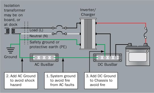
1. Before installing a charging device, confirm that there is a good connection between AC and DC grounds. If there is not a good connection, the charger/inverter grounding, when it is installed, may become the main connection between AC and DC grounds and must be sized for the boat's entire electrical system in order to avoid the risk of shock or fire. The AC grounding system and the DC grounding system should be firmly connected at a main grounding bus or at the engine block.,/p>

These connections help prevent faults in a boat's wiring from becoming lethal leakage currents that flow into the surrounding water or energize exposed metal on a boat. Some boat builders omit this grounding connection as a means of reducing galvanic corrosion resulting from coupling to adjacent vessels through the power system. A better way of preventing galvanic corrosion is to install this ground connection and install a galvanic isolator or isolation transformer in the AC power system.,/p>

When Installing Charger, Inverter, or Inverter/Charger Follow A-20 and A-25

A-20 and A-25 contain specific installation directions that are not described in E-11.

2. Install the AC wiring to the charger or inverter including an AC grounding conductor of a size equal to the current carrying conductors unless the circuit exceeds 30A, in which case the grounding conductor may be one size smaller (E11.16.1.3.8.2). This is the typical grounding conductor that you would see with any AC appliance and returns with the other AC conductors to the power distribution panel.

3. Install a DC grounding conductor sized not less than one size smaller than the DC positive conductor and have a capacity such that the DC positive fuse has an amperage rating not greater than 135% of the current rating of this grounding wire. As a practical matter, this wire will be much larger than the AC grounding conductor. This requirement is the latest addition to the standards when it was discovered that faults in the DC side of an inverter or charger could provide sustained high currents that could start a fire from overheating the AC grounding conductor.

Image

Discussion

The rules for grounding electrical systems have evolved over time. Boat builders, installers, and electricians continue to recognize hazards and increase safety measures. Battery chargers were originally treated like any other small appliance, first without having any safety ground as was common through the 1950's, and then by adding a safety ground to reduce shock hazards during faults.

It was found that faults in the DC wiring or the DC side of chargers could generate fires because high current could flow back from the batteries, so a fuse was added between inverters or chargers and the battery system. As the capacity of chargers increased, and with the introduction of inverters, these DC fuses became quite large. It was then determined that a fire hazard exists when a DC fault in a charger or inverter can pass DC current into the AC safety ground wire. The AC safety ground was not sized for the high DC currents, so a high capacity DC grounding wire is now required by standards A-20 and A-25.

Now three critical grounding wires for these systems have been identified. This may seem excessive, but this combination of grounding conductors has been shown to give protection against a wide variety of faults.

~Rich
User avatar
mike uk
First Officer
Posts: 214
Joined: Thu Sep 23, 2004 1:42 pm
Location: England 26X

Re: Inverter install

Post by mike uk »

Rich

What a brilliant post!

You get the prize for the best post ever!

If you happen to be in North West England anytime let me know and I'll buy you a pint (and if you are really lucky, I'll let you check the wiring on my boat :D )

Regards
Mike
Post Reply