

One only has to visit a boat yard and look at the under carriages of various sailboats. Those big keels are there for a reason..They don't hang all that structure under there for the fun of it..The "X" & "M" boats have compromised sailing ability in order to achieve high speeds under power. As others have suggested, adding 2 or 3 inches to the leading edge of the CB would undoubtedly improve sailing ability and it might improve tracking while motoring at high speed too. Many high-speed hulls have some means to get a little "bite" during turns. You just don't want to overdue it and trip the boat.
The Lancer 27PS, a sailboat that mounts high power engines and planes (you didn't think Macs were the only ones did you?) leave a portion of their iron swing keels exposed to improve tracking. They also sit MUCH higher on there trailers..
Swing Keel mod (Skeg maybe?)
-
Gerald Gordon

- First Officer
- Posts: 284
- Joined: Fri Feb 27, 2004 9:58 pm
- Location: O'ahu, Hawai'i
Many of the opinions expressed regarding a CB mod seem to contradict one another. Lots of speculation; not a lot of data. It’s time for some action. Build it and it will sail. The CB could be built to accommodate the cross members of the trailer. Like an upside down V. Then test it. 12” might be too much depth. So let’s try 6”. If beaching your boat is important then this may not be a solution to the crabbing. I agree, the X needs a bite to stay the course. The keel addition could look like an upside down T. The small lip on the edge of the extension would offer still more slipping resistance.
-
Dimitri-2000X-Tampa

- Admiral
- Posts: 2043
- Joined: Fri Jan 02, 2004 5:36 am
- Sailboat: MacGregor 26X
- Location: Tampa, Florida 2000 Mercury BigFoot 50HP 4-Stroke on 26X hull# 3575.B000
I can tell you that the ballast will not drain out with the boat on a lift...been there, tried that. I guess it is just too horizontal because only a little bit of the ballast water comes out which leaves you in a non stable condition.Frank C wrote:Seems to me that lifting with full ballast is a question of "how quickly?" As long as I opened the gate valve when beginning the lift, I wouldn't be too concerned. Ballast tank should be 90% empty within <5 minutes.eric3a wrote:Hmm.
Didn't think about that. I doubt it would harm the boat, but will need to check I guess.
The reason I would want to do that (lift w/full ballast) is so I don't have to run around at full speed for a while just to empty my ballast tank. Only to fill it back up as soon as I put the boat back in anyway.
Eric
Every once in a while, I do leave ballast in when lifting the boat. I don't think it causes any undue stresses anywhere...we have had this discussion before...these boats are designed to handle a heck of a lot more stress than lifting it with a full ballast. And it certainly causes no stress to my 10,000 lb capacity boat lift.
However, I will go back out again within a week to empty the ballast. I'm a firm believer in the empty ballast tank most of the time camp. If you leave water in there, especially sea water, you are going to end up with a stinky ballast tank after a few weeks. If you regularly drain it, then it always stays fresh and clean. For me, its not a big deal since the last couple miles to my house are in a channel where its very difficult to sail, so it is very easy to dump ballast on the last leg of any trip. Every once in a while if the wind is just right (rare), then I'll sail back home through the channel ... and those are the cases where I might put it back full on the lift since I never went fast enough to drain it.
I do like to sail most of the time. On my trip last week, I only went fast on the last 1-2 miles of a 120 mile trip...and just to empty the ballast.
-
Frank C
-
Dimitri-2000X-Tampa
- Admiral
- Posts: 2043
- Joined: Fri Jan 02, 2004 5:36 am
- Sailboat: MacGregor 26X
- Location: Tampa, Florida 2000 Mercury BigFoot 50HP 4-Stroke on 26X hull# 3575.B000
Sorry, didn't see that one.Frank C wrote:Dimitri,
What about the earlier comment, as below?
Frank C wrote: . . . This means you need a half-mile speed run each evening to empty the ballast,
. . . or else you'll need to orient bow-up (i.e., the lift's bunks) and drain it after starting your lift.
At first glance, unless you build some custom wedges for the bunks to angle the bow up, you would need to wrap the cable tighter on the front part of the bunks. This would put a permanent slope on the lift which probably would drain the ballast....HOWEVER, I would certainly not be comfortable doing this as I would be worried the boat might fall off the lift in rough conditions. The mac is such a big light balloon that it swings around much more than heavier boats. I tend to tie my cradle to the pilings a lot more than my neighbors do.
-
Gerald Gordon
- First Officer
- Posts: 284
- Joined: Fri Feb 27, 2004 9:58 pm
- Location: O'ahu, Hawai'i
To continue...
I plan to modify my X's centerboard so that it will function like a daggerboard. The board will articulate about 10 inches.
I was reading up on the Rhodes 22. There was a discussion on how they have built an asym diamondboard. From what I got was that the lift portion of the wing/fin, which seems to be the thick part, has been moved to the end of the board and the slender part comes first.
What's up with that?
http://www.rhodes22.com/keel_diamond_small.html
-
Gerald Gordon
- First Officer
- Posts: 284
- Joined: Fri Feb 27, 2004 9:58 pm
- Location: O'ahu, Hawai'i
-
Gerald Gordon
- First Officer
- Posts: 284
- Joined: Fri Feb 27, 2004 9:58 pm
- Location: O'ahu, Hawai'i
Centerboard Modification ’99 26 X
CONCEPT:
A vertical thin CB does not produce sufficient resistance to prevent the X from crabbing. Deploying the CB horizontally will expose 76 1/2” x10” (however much resistance that creates) and will keep 4” in the CB trunk for support.
This CB is designed to be suspended, not rigidly fixed, from a telescoping 1.5” SS welded tube (piston) which slides in a1.5” SS Schedule 40 pipe (cylinder). The sides of the trunk are used for lateral support much like the stock CB wedges itself for support. The CB can remain completely in the trunk for fast motoring and beaching or be lowered any distance up to 10”.
Here is a parts list and pictures of how I did the mod.
1 piece @ $23.15/piece
Stainless T-304
Pipe Schedule 40
1.5" nom. (1.9" OD x 0.15" Wall x 1.61" ID)
Cut to: 12"
-------------------------------------------------
1 piece @ $27.63/piece
Stainless T-304
Seamless Tube
0.75" x 0.065" x 0.62"
Cut to: 24"
-------------------------------------------------
1 piece @ $8.53/piece
Stainless T-304
Round
0.5"
Cut to: 24"
-------------------------------------------------
1 piece @ $39.39/piece
Stainless T-304
Welded Tube
1.5" x 0.12" x 1.26"
Cut to: 36"
-------------------------------------------------
Fibers Hair body putty. (Not Bondo, it absorbs water)
Fiber Strand
Ultra Glass
Mat
Cloth
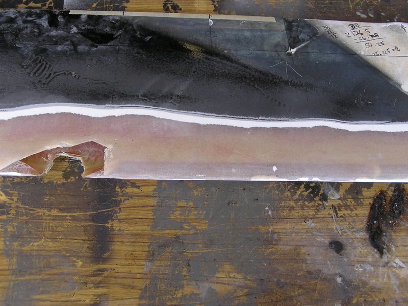
Thanks to Billy for measuring the CB. My CB is 76 1/2”x14”x1 9/16” It weighs 26lbs.
My stock board. The pivot pin wore a huge hole into the board.
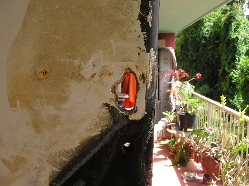
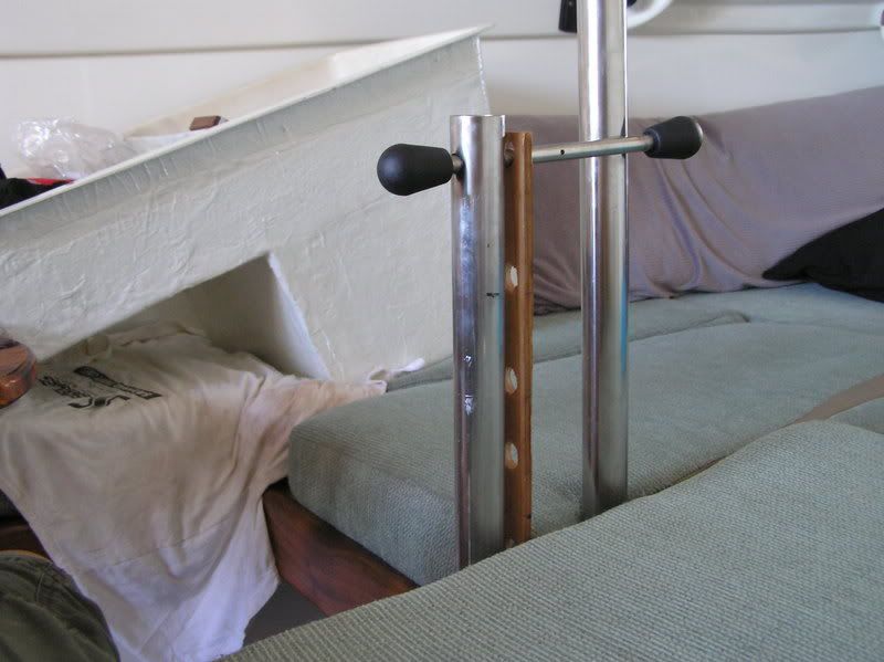
Here is the 1.5” thru hole inside the cabin on top of the CB trunk. This hole is centered 4” from the stern bolt holding the compression post. Try to get the hole in the middle of the trunk (mine isn’t). There’s about 1.9”-2.0” of space at this point in the trunk. After this point the trunk narrows and conforms to the top of the CB. I used a dremel to enlarge to 1.9+/-”.
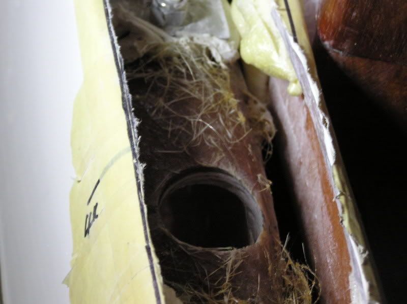
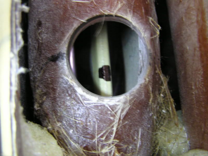
I reinstalled the CB in order to mark the exact location for the piston tube.
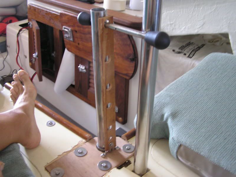
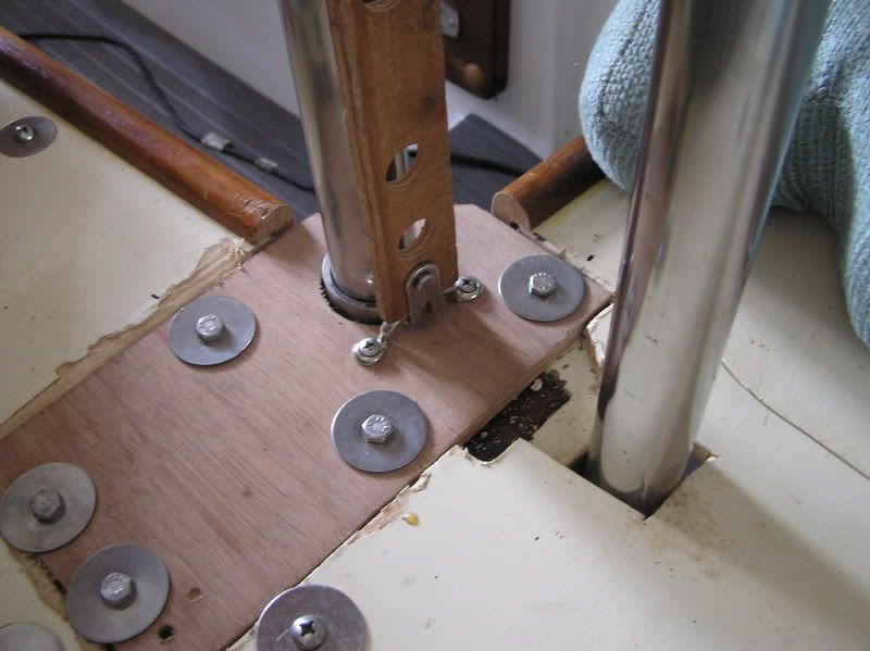
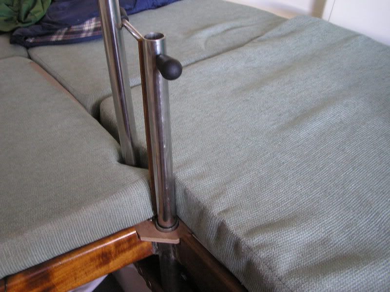
I’ve installed the Schedule 40 pipe onto the centerboard trunk. You see both the compression post and the cylinder pipe.
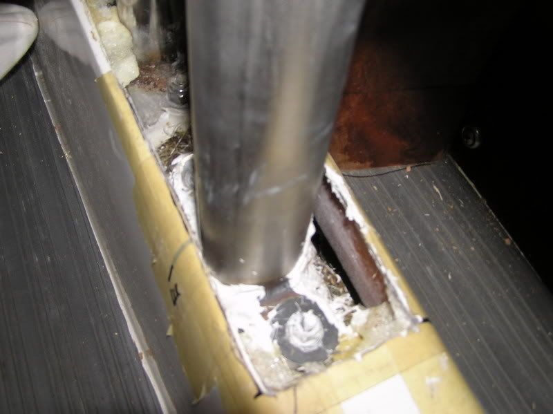
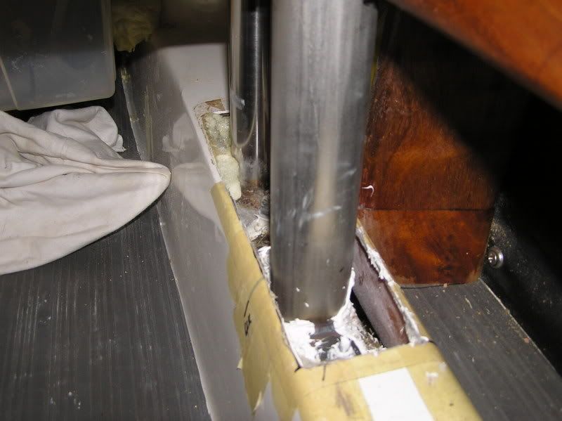
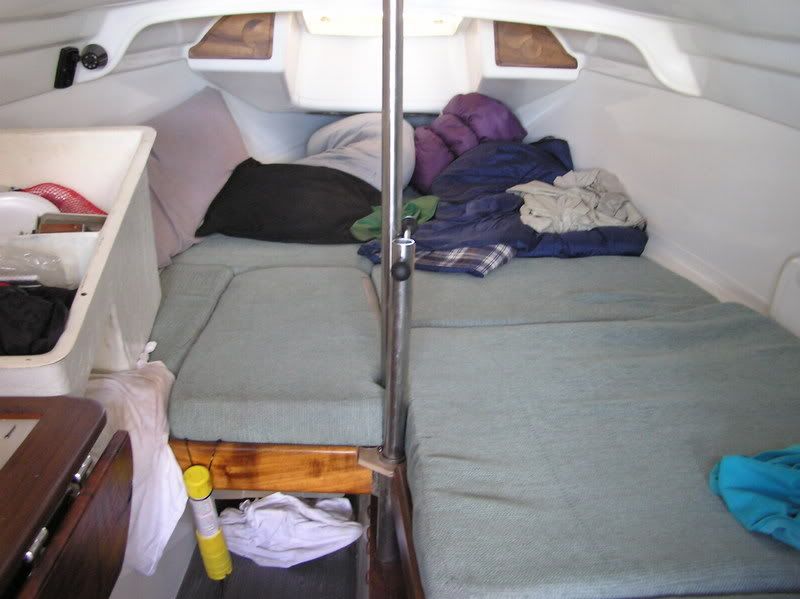
This is skipping ahead and shows how it looks in the cabin.
CENTERBOARD
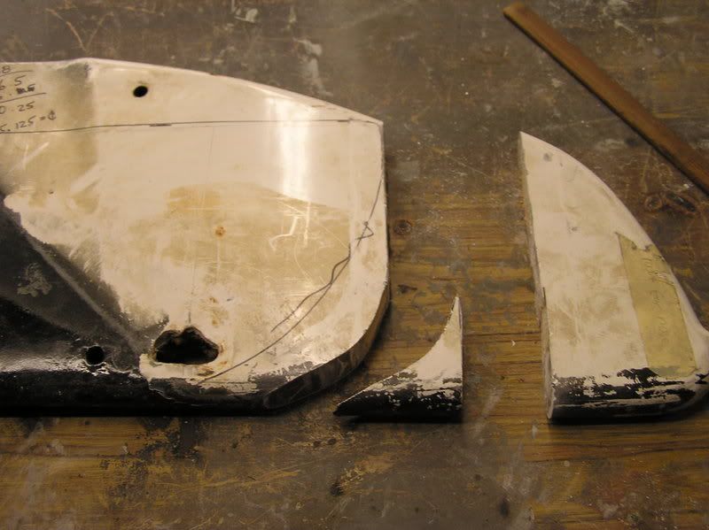
I cut the nose from the CB. I’ll epoxy it into the boat to reduce any turbulence at the front part of the CB trunk.
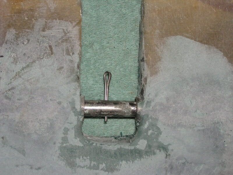
I’ll fill the CB to be 1 9/16+/-” all along the bottom. Then I’ll install the new CB hanger. I’ll use the SS tube and the SS rod for that. The hardware is imbedded into the CB with mat and faired and glassed with 3 layers of cloth. The rod can slide back to release the CB for removal. A cotter pin prevents the CB from coming off the rod.
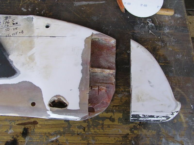
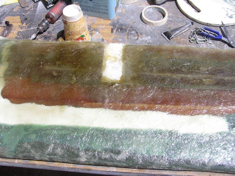
I made a section at the nose for body putty. I’m going to reshape that part of the board. I also sanded off the gel coat for better fiberglass adhesion. The nose piece is 4.5”X10”
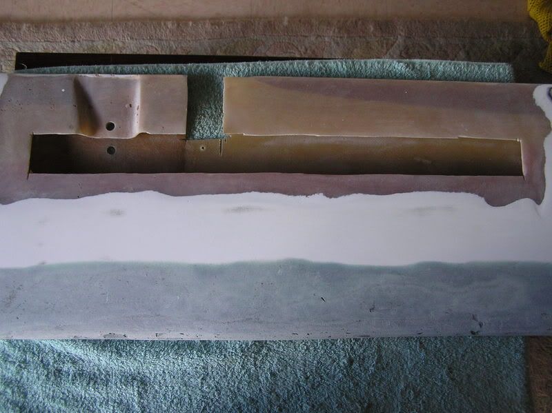
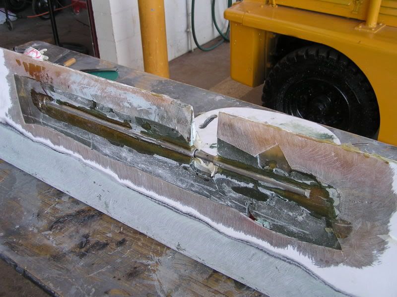
3.5” from the top of the CB I cut out 16.25” x2”. There is also 1 5/8” entry for the piston rod, which operates the board. I will embed a 16” SS tube .062 ID to act as a sleeve for the .5” SS rod that will support the board. I filled the cavity with fiber hair.
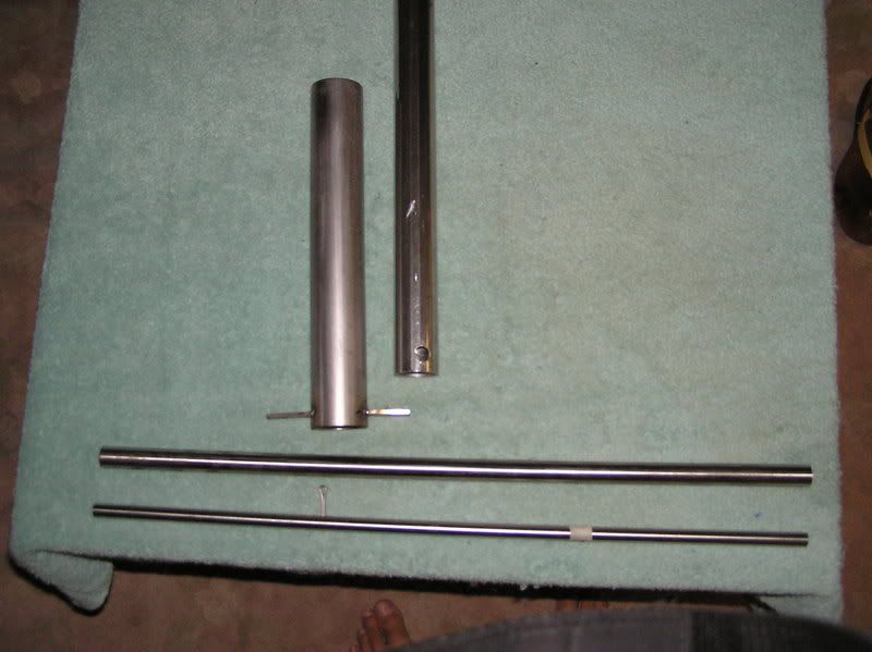
Here is the hardware that I’ll install into the CB and the boat.
Cylinder Sleeve
Piston rod
Hanger sleeve
Hanger rod
Cotter pin
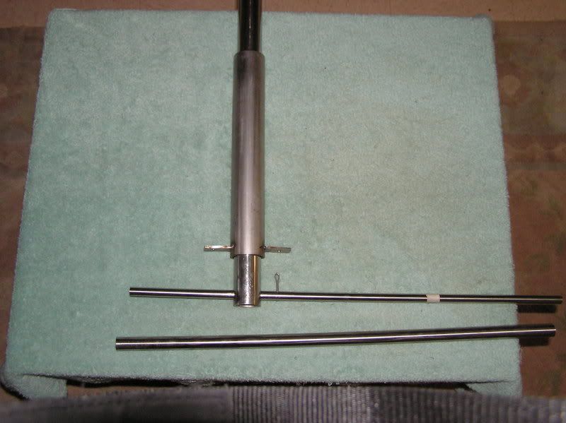
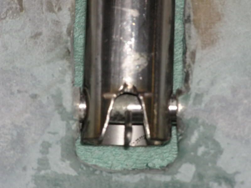
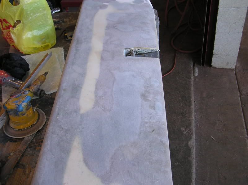
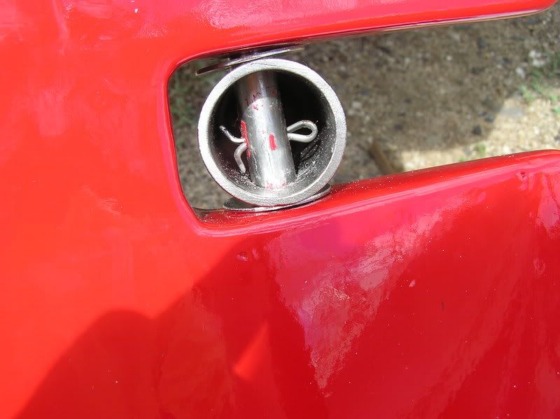
I’ve installed the hardware into the CB. You can see the cam partially open and closed

I have two more steps to complete. First, I’ll fill the board with resin. Second, I’ll cover the CB with two (?) layers of cloth and colored resin.
Holly Smoke, Batman,
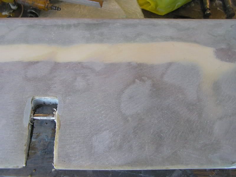
As I was filling the CB with resin it ran into the hanger. I had to cut the hanger hardware out. My very good friend, Curtiss, then reset the hardware with mat instead of fiber hair. He enlarged the hardware opening by grinding out some of the fiber hair. The mat makes the connection much much stronger.
Here’s the mat lay up.
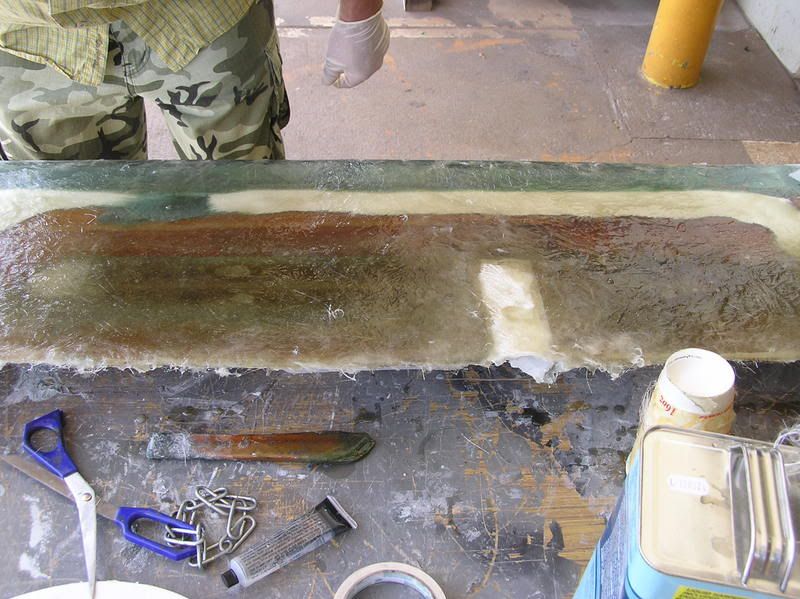

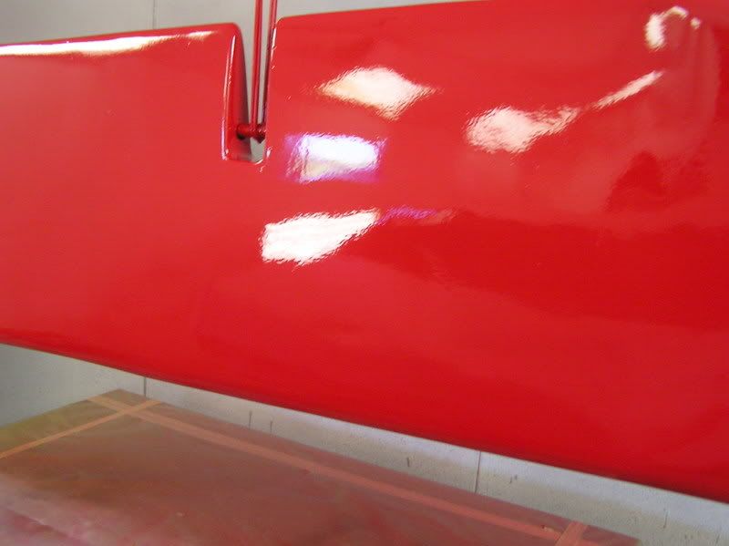
The board has been sanded and is ready for two layers of cloth and red colored resin.
Here the board has been painted red
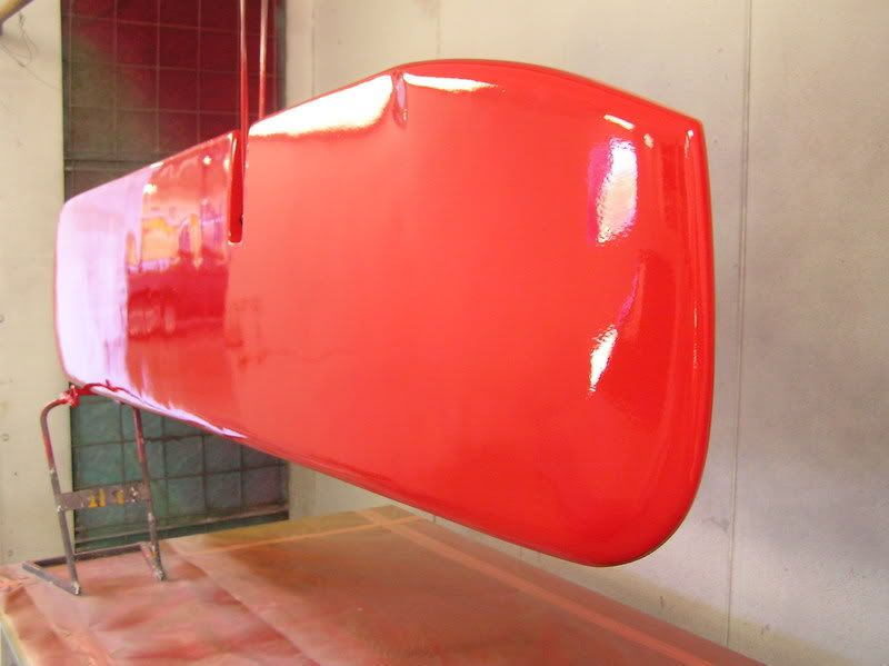
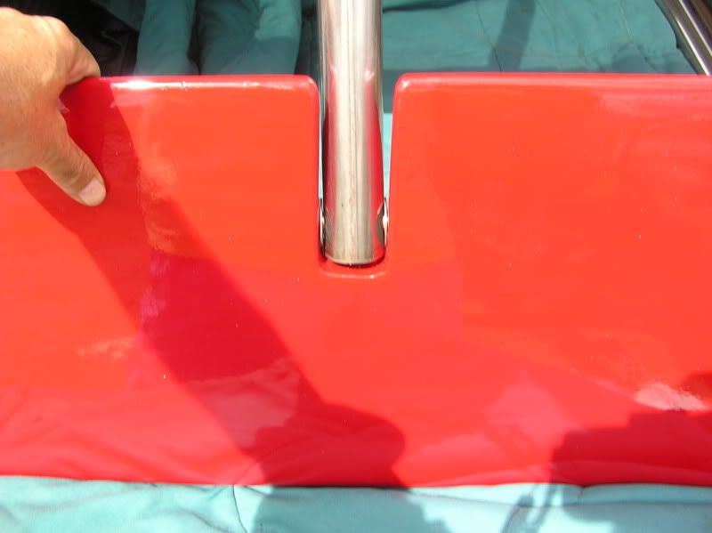
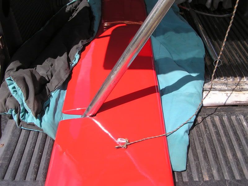
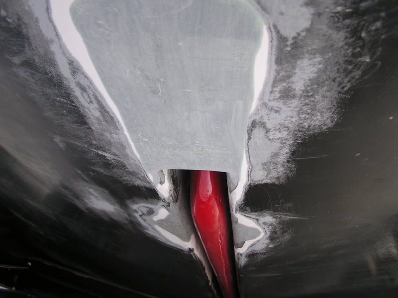
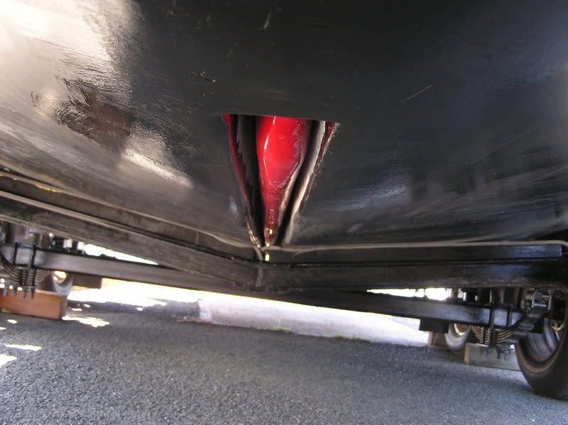
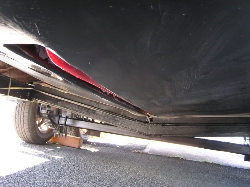
I just installed the board into the trunk. I did not want to jack up the boat, so Curtiss and I put the boat in the water and dove a bit. I am really surprised about the weight. The board is about 65 lbs. on land, but in the water I can hold it with one hand, one finger. That means that there will not be a lot of stress on the mounting mechanism (good deal).
The board is installed. The front section of the CB which I cut off has been fiberglassed into the CB trunk and the indentations of the holding bracket pin have been filled.
Well, there you have it. It’s time to taste the soup.
CONCEPT:
A vertical thin CB does not produce sufficient resistance to prevent the X from crabbing. Deploying the CB horizontally will expose 76 1/2” x10” (however much resistance that creates) and will keep 4” in the CB trunk for support.
This CB is designed to be suspended, not rigidly fixed, from a telescoping 1.5” SS welded tube (piston) which slides in a1.5” SS Schedule 40 pipe (cylinder). The sides of the trunk are used for lateral support much like the stock CB wedges itself for support. The CB can remain completely in the trunk for fast motoring and beaching or be lowered any distance up to 10”.
Here is a parts list and pictures of how I did the mod.
1 piece @ $23.15/piece
Stainless T-304
Pipe Schedule 40
1.5" nom. (1.9" OD x 0.15" Wall x 1.61" ID)
Cut to: 12"
-------------------------------------------------
1 piece @ $27.63/piece
Stainless T-304
Seamless Tube
0.75" x 0.065" x 0.62"
Cut to: 24"
-------------------------------------------------
1 piece @ $8.53/piece
Stainless T-304
Round
0.5"
Cut to: 24"
-------------------------------------------------
1 piece @ $39.39/piece
Stainless T-304
Welded Tube
1.5" x 0.12" x 1.26"
Cut to: 36"
-------------------------------------------------
Fibers Hair body putty. (Not Bondo, it absorbs water)
Fiber Strand
Ultra Glass
Mat
Cloth
Thanks to Billy for measuring the CB. My CB is 76 1/2”x14”x1 9/16” It weighs 26lbs.
My stock board. The pivot pin wore a huge hole into the board.
Here is the 1.5” thru hole inside the cabin on top of the CB trunk. This hole is centered 4” from the stern bolt holding the compression post. Try to get the hole in the middle of the trunk (mine isn’t). There’s about 1.9”-2.0” of space at this point in the trunk. After this point the trunk narrows and conforms to the top of the CB. I used a dremel to enlarge to 1.9+/-”.
I reinstalled the CB in order to mark the exact location for the piston tube.
I’ve installed the Schedule 40 pipe onto the centerboard trunk. You see both the compression post and the cylinder pipe.
This is skipping ahead and shows how it looks in the cabin.
CENTERBOARD
I cut the nose from the CB. I’ll epoxy it into the boat to reduce any turbulence at the front part of the CB trunk.
I’ll fill the CB to be 1 9/16+/-” all along the bottom. Then I’ll install the new CB hanger. I’ll use the SS tube and the SS rod for that. The hardware is imbedded into the CB with mat and faired and glassed with 3 layers of cloth. The rod can slide back to release the CB for removal. A cotter pin prevents the CB from coming off the rod.
I made a section at the nose for body putty. I’m going to reshape that part of the board. I also sanded off the gel coat for better fiberglass adhesion. The nose piece is 4.5”X10”
3.5” from the top of the CB I cut out 16.25” x2”. There is also 1 5/8” entry for the piston rod, which operates the board. I will embed a 16” SS tube .062 ID to act as a sleeve for the .5” SS rod that will support the board. I filled the cavity with fiber hair.
Here is the hardware that I’ll install into the CB and the boat.
Cylinder Sleeve
Piston rod
Hanger sleeve
Hanger rod
Cotter pin
I’ve installed the hardware into the CB. You can see the cam partially open and closed
I have two more steps to complete. First, I’ll fill the board with resin. Second, I’ll cover the CB with two (?) layers of cloth and colored resin.
Holly Smoke, Batman,
As I was filling the CB with resin it ran into the hanger. I had to cut the hanger hardware out. My very good friend, Curtiss, then reset the hardware with mat instead of fiber hair. He enlarged the hardware opening by grinding out some of the fiber hair. The mat makes the connection much much stronger.
Here’s the mat lay up.
The board has been sanded and is ready for two layers of cloth and red colored resin.
Here the board has been painted red
I just installed the board into the trunk. I did not want to jack up the boat, so Curtiss and I put the boat in the water and dove a bit. I am really surprised about the weight. The board is about 65 lbs. on land, but in the water I can hold it with one hand, one finger. That means that there will not be a lot of stress on the mounting mechanism (good deal).
The board is installed. The front section of the CB which I cut off has been fiberglassed into the CB trunk and the indentations of the holding bracket pin have been filled.
Well, there you have it. It’s time to taste the soup.
-
MARK PASSMORE

- First Officer
- Posts: 217
- Joined: Fri Jun 22, 2007 6:38 pm
- Location: Lake Lanier GA - 07 MAC 26M YAMAHA T60 "faster blue hull"
-
Erik Hardtle

- First Officer
- Posts: 408
- Joined: Sat Jan 03, 2004 4:45 am
- Sailboat: MacGregor 26X
- Location: New Bern, NC
- Contact:
Weighted CB
Whoa...
and I thought I had gone off the deep end with my centerboard mod...
http://macgregorsailors.com/cgi-bin/mod ... record=460

Good luck, hope it work as desired.
Erik
and I thought I had gone off the deep end with my centerboard mod...
http://macgregorsailors.com/cgi-bin/mod ... record=460
Good luck, hope it work as desired.
Erik