Page 2 of 8
Re: DIY Shore Power Install
Posted: Fri Oct 10, 2014 10:35 am
by Wind Chime
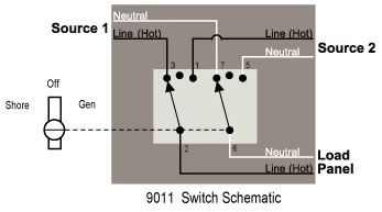
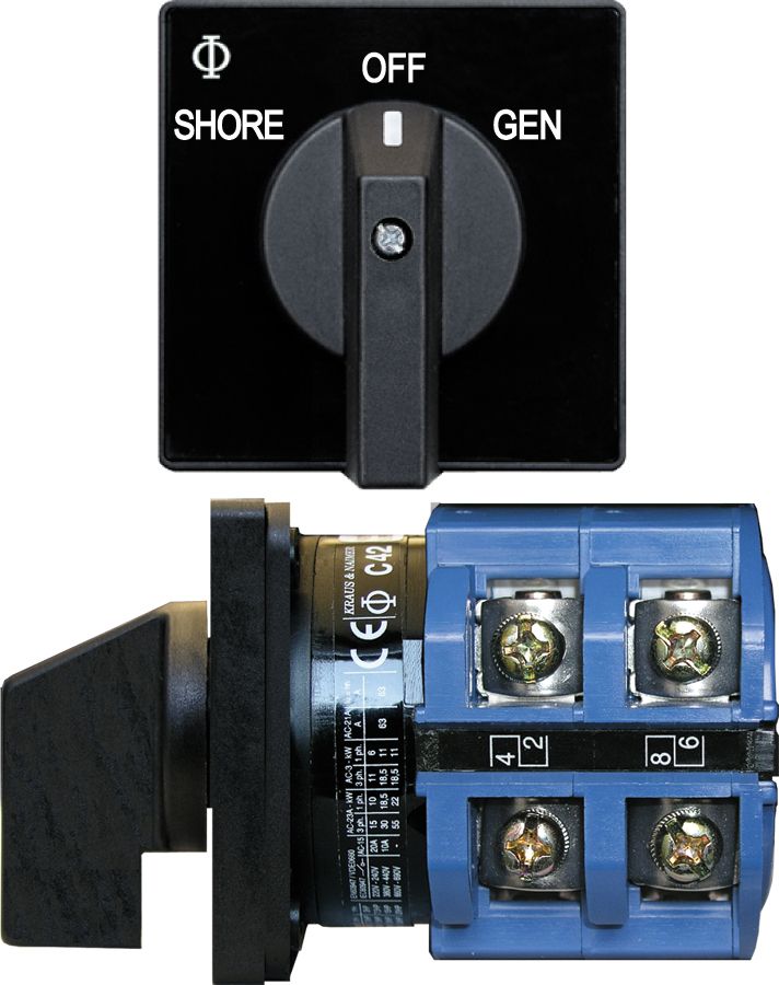
Has anyone had any experience with an A/C "Source-Selector" switch, like the Blue Sea 9011 I am suggesting?
This is kind of like an "A-B-OFF" battery switch. Looks to me like it is installed "in-line"
before the Blue Sea 8043 breaker box? (with wires connected from both the SHORE and the GEN (INVERTER in my case)
* We have a 300 watt inverter I would like to install through the same system to switch the outlets between: A/C (shore power) and D/C (inverter).
6) Inverter Option:
Source Selection Switch: (Blue Sea #303SSEL-B)
http://www.go2marine.com/product/99867F
http://assets.bluesea.com/files/resourc ... s/6670.pdf
Blue Sea Systems, AC Source Selection Rotary Switch. Heavy duty industrial rated switches provide a compact and intuitive solution for safely managing AC sources when circuit protection is provided elsewhere.
•Switches 2 or 3 120 or 230 Volt AC sources
•Compact solution when circuit protection is provided elsewhere
•Allows connecting one of up to 3 different AC sources to one circuit
•Intuitive function - One hand operation
•UL listed
•600 Volt AC max
Re: DIY Shore Power Install
Posted: Fri Oct 10, 2014 11:34 am
by Tomfoolery
Wind Chime wrote:This is the first I have heard about needing a "30A transfer switch" ? What is this and why?
From what I have read, a selector switch (below) isntalled "before" the breaker box is all that is required to swich from shore to inverted AC. Not the case?
Functionally the same thing. Transfer switches are used in building and equipment to switch between utility power and a generator (usually), though I've used large ones to select between two different utility supplies for fixed equipment.
That's what you need (the selector switch), installed between the power inlet and the main breaker of the panel, with the inverter powering the other side. The 30A rating is because it's a 30A utility supply and main breaker, even if the inverter is only good to a few amps.
It breaks before it makes (off in the middle), which is important.
This crane has two sources of power, from the utility (it's at the Bonneville Dam), using a very large version of that switch, but functionally it works the same way. I'm afraid I don't have all the marine terminology right, as my experience is 500:1 industrial to marine.


Re: DIY Shore Power Install
Posted: Fri Oct 10, 2014 11:48 am
by Wind Chime
Thanks Tom,
It first sounded like maybe I had missied a vital component (30 amp transfer switch) but it sounds like the Blue Sea "Selector Switch" I am suggesting will do the same thing when intalled between the Shore-Power through hull and the breaker panel.
Re: DIY Shore Power Install
Posted: Fri Oct 10, 2014 11:55 am
by Wind Chime
Does anyone want to take a crack at reviewing for me: free floating grounding for A/C verse D/C, and also ground bonding.
A/C ground to shore - D/C ground to battery - no bonding on Mac's?
Re: DIY Shore Power Install
Posted: Fri Oct 10, 2014 12:36 pm
by Tomfoolery
Wind Chime wrote:Does anyone want to take a crack at reviewing: free floating grounding for A/C verse D/C, and also ground bonding.
A/C ground to shore - D/C ground to battery - no bonding on Mac's?
Bond them.
http://www.safeelectricity.org/componen ... ticle/1589
What killed Lucas Ritz was a small boat rafted to a big boat, with an extension cord between them providing power to the small boat, and the DC system not bonded to the AC system. A chafed hot wire energized the -DC bits, which then leaked into the surrounding fresh water, creating a voltage gradient radiating out from that point. Human bodies have a lower DC resistance than fresh water across the same distance, so more current flowed through him than through the water around him, with enough current through him to paralyze him. I believe he was actually electrocuted, but most folks in the same situation drown when they can't move.
There's a graphic at the 6:00 mark that was used in the original presentation on this, with a detailed explanation, but I don't know where to find that (different) video at this time. Around the 9:00 mark starts a little bit of technical discussion with a few slides of bad wiring, but the other video (if I can find it) has much more detail on this.
My FIL tells me it used to be common practice to snip the shore power ground because leakage current from
the other guy's boat would eat up their props and shafts and other metal under the water.

I sent him the Ritz presentation for his Power Squadron flotilla a few years back, and he commented to me on how almost everyone there agreed that it was 'just the way it was' back then, and many (maybe most) were surprised about the dangers, including ESD. Granted, it's mostly a bunch of older gentlemen and their admirals, but it is/was the prevailing 'wisdom', if you can call it that.
Ahh, here it is. It was a long(ish) webinar, but worth watching.
http://www.abycinc.org/whyabyc/esd_I.cfm
Re: DIY Shore Power Install
Posted: Fri Oct 10, 2014 1:14 pm
by Wind Chime
Thanks Tom,
I'll watch both of these videos tonight at home.
A factory Mac does not come with the ground bonded, does it? Outboard engine?
How would you bond the A/C system on a Mac? and is this standrd practice for thsoe that have had aftermarket shorepower installations?
... or is this getting complicated only because I am including the inverter into the same outlets?
FYI: got this info below from this site:
http://www.boatwiring.org/minimize-electrical-risk/
When you switch between a generator, inverter or shore power, the grounding connection must switch too. (If the boat is on shore power the green wire connects to the underwater metal hardware of other boats on the same shore power system. This creates a galvanic cell that promotes stray current and galvanic corrosion. A galvanic isolator on the green wire allows passage of AC but not DC, thereby isolating the boat from the others. A more sophisticated device for the same purpose is called an isolation transformer.)
Re: DIY Shore Power Install
Posted: Fri Oct 10, 2014 1:45 pm
by RobertB
I have been reading up on bonding. It seems, there is not much to do on our boats. In theory, all metal parts in contact with the water must be "bonded" together (connected electrically in a low resistance manner). We have a non-conductive hull. All my through hulls are non-metal. I have no metal keel. So, all we have is the motor. And I believe most of us only have the two wires hooked to the motor charging/starting circuit - and I assume that the negative lead is connected to the motor case (but have no proof on hand). So, in our case, bonding is connecting the AC ground lead from shore and in the boat wiring (green), to any AC frame grounds (like on a battery charger), and finally to the battery negative cable that in turn is directly connected to the engine.
Re: DIY Shore Power Install
Posted: Fri Oct 10, 2014 1:57 pm
by Wind Chime
Thanks Robert,
My research is pointing me in the same direction as you.
But, is it as simple as running a wire from the A/C Shore-Power ground (green wire) to the D/C negative ground pole of the battery terminal (black wire) -thereby bonding the continuity between the A/C & D/C grounds and everything that is connect ?
We must have a certified ABYC electrican on this board, don't we?
Re: DIY Shore Power Install
Posted: Fri Oct 10, 2014 3:47 pm
by RobertB
A certified electrician would take all the fun out of it.

I recommend you not hook directly to the battery, a stack-up of terminals is a bad practice, and use a terminal block instead. I have a fuse block on my VW Beetle (really my wife's) for major loads from the battery (located on the battery housing) where some inventive factory worker stacked three fuses to add up to the value of the SINGLE fuse that was supposed to be installed. Over time, resitance between the stacked fuses built up and created a sequential failure that torched the whole fuse block. German engineering built in Mexico

Re: DIY Shore Power Install
Posted: Fri Oct 10, 2014 3:53 pm
by Wind Chime
So going from: green A/C on breaker panel - to Black D/C on negative bus bar, would suffice bonding requirements?
Re: DIY Shore Power Install
Posted: Fri Oct 10, 2014 3:54 pm
by RobertB
How does this panel look?
https://www.bluesea.com/products/1206/1 ... _Positions $107 from Amazon.
I really want branch breakers but could just wire the charger off the main and leave the branch breakers for the AC outlet and the air conditioning.
Re: DIY Shore Power Install
Posted: Fri Oct 10, 2014 4:00 pm
by RobertB
Wind Chime wrote:So going from: green A/C on breaker panel - to Black D/C on negative bus bar, would suffice bonding requirements?
Don't forget any case grounds on a battery charger.
So, my understanding, stated to receive corrective beating should I be wrong, is that AC 120V main wires (black and white) should remain isolated from all earth and case grounds (unlike home wiring where in the primary panel the white is linked to the green, but not in the sub-panels), AC ground (green wire) should be connected to all case grounds and the DC negative and this in turn should stay connected to the engine that is the only metal boat component in the water. I also think it would be a good idea to verify proper polarity of the AC shore supply (although for my application it may not be necessary).
Re: DIY Shore Power Install
Posted: Sat Oct 11, 2014 2:57 am
by raycarlson
don't connect anything in your a/c system to anything in your d/c system, ground a/c to only the shore power ground on plug. Buy 5 dollar polarity-ground checker plug at home depot to check your shore power supply for safety-servicability
Re: DIY Shore Power Install
Posted: Sat Oct 11, 2014 7:40 am
by RobertB
raycarlson wrote:don't connect anything in your a/c system to anything in your d/c system, ground a/c to only the shore power ground on plug. Buy 5 dollar polarity-ground checker plug at home depot to check your shore power supply for safety-servicability
So, after all the discussion about AC to DC in this and another active thread (Im Back....Bimini..), you would not connect the green ground wire from the shore power AC to the boat DC negative? I am beginning to see two distinctly different theories/opinions on this.
The point to consider, with a battery charger, I already have something in my AC system connected to something in my DC system.
Already referenced
http://www.westmarine.com/WestAdvisor/T ... Conditions
Re: DIY Shore Power Install
Posted: Sat Oct 11, 2014 7:54 am
by Sumner
raycarlson wrote:don't connect anything in your a/c system to anything in your d/c system, ground a/c to only the shore power ground on plug. Buy 5 dollar polarity-ground checker plug at home depot to check your shore power supply for safety-servicability
Ray, Robert has it right...
 http://www.westmarine.com/WestAdvisor/T ... Conditions
Where there can be confusion is on the AC side where people sometimes call the white neutral ground when it is the safety green wire that is the only ground. The white neutral and the green safety ground are connected together back at the source of power, which would be the main panel at the marina where their power comes in from the utility and no where else.
 http://www.westmarine.com/WestAdvisor/M ... ng-Systems
In the picture above you can see the green safety going to the DC ground where it says "to engine negative terminal" which would also be going to the negative side of the battery.
The following link also explains this and has a good picture of proper wiring....
http://qualitymarineservices.net/Neutra ... 2-2005.pdf
AC wiring is pretty straight forward and so is DC wiring but on a boat where you can have both it is much more confusing and if one is confused at all maybe having help is a very good idea. It doesn't help also that the wire colors between the two are different.
Sumner
============================
Our MacGregor 26-S
Our Endeavour 37
Our Trips to Utah, Idaho, Canada, Florida
Mac-Venture Links


