Page 4 of 5

Re: 3 Guesses. First 2 don't count.

Posted: Mon Oct 26, 2020 4:57 pm
by NiceAft
finding 41,

I am intrigued by your decision to use a whale fin design for a rudder.

You posted "As for Whale Fin Rudders and Tubercals. If you Google you will find some stuff I've written on another forum and some other peoples testing on fans and wind turbines. You can also look into the air disrupt strip (Not sure what it's called.) on the top of airplane wings. " It seems that the fan and wind turbine examples create lift, thus making them turn while remaining stationary, not something desirable in a rudder. I am not an engineer, so my observation is strictly non professional. It just struck me as something more than different. If it works, terrific.

Re: CAD and Raw Prints Complete

Posted: Mon Oct 26, 2020 5:17 pm
by Jimmyt
Inquisitor wrote: Mon Oct 26, 2020 3:11 pm Just finished the final printing.

Image 1 - All ABS daggerboard foil sections. I used more plastic than I initially thought. I printed them more robust than they really have to be as simple forms for the fiberglass. Large, thin ABS prints tend to oil can and warp easily.
Image 2 - The aft/top portion of the daggerboard where the lifting line mounts. Include custom Nylon sheave and bolt (untightened) for 2:1 lifting.

Current Outlay
2.8 Kg - ABS 3D Print Filament - $28.00
12 g - Nylon 3D Print Filament - $0.50
(1) 1/4" x 5/16" x 3/4" Bronze Bushing - $2.80
(1) 1/4" x 2.5" SS Course thread bolt - $0.74
(1) 1/4" SS Flat Washer - $0.13
Total $31.36
That looks amazing! And the price is unbeatable! Are you going to run a port/starboard glass spine between the fore and aft pieces, or was there another reason you split the foil? Just interested in the process.

Thanks for the good thoughts. We've been lucky so far this season. A few in our neighborhood have had minor issues. One of the wife's coworkers had a tree split their house lengthwise. Fortunately, he and the wife and kids were ok. They are about 5 miles north of us. Hope this will be the last one this year. My buddy on Wolf Bay hot about 3.5 ft of water in his workshop in his new place. Lots of tool loss. His neighborhood took a big hit.

The workshop is nice; even when we're huddled down there waiting for the wind to subside...

Re: CAD and Raw Prints Complete

Posted: Mon Oct 26, 2020 6:00 pm
by Inquisitor
Jimmyt wrote: Mon Oct 26, 2020 5:17 pm Are you going to run a port/starboard glass spine between the fore and aft pieces, or was there another reason you split the foil? Just interested in the process.

Thanks for the good thoughts. We've been lucky so far this season. A few in our neighborhood have had minor issues. One of the wife's coworkers had a tree split their house lengthwise. Fortunately, he and the wife and kids were ok. They are about 5 miles north of us. Hope this will be the last one this year. My buddy on Wolf Bay hot about 3.5 ft of water in his workshop in his new place. Lots of tool loss. His neighborhood took a big hit.

The workshop is nice; even when we're huddled down there waiting for the wind to subside...
Just checked... that's got to be an eerie feeling something that deadly bearing down on you. Do you all evacuate? Take care!

Some is the constraint of my printer 220x250mm bed. The back pieces rotated 35 degrees just fit. Can do two at a time and a couple of front pieces in the other corners. But the main reason you guessed right is a spar like a plane wing has. It'll be just under 1.5". The third post back on page one, has them all lined up with that 1.5" spacing.

Image

In the image, the green is the wood. Note it is 0.1" relieved (with bevels) from the contour of the foil. In this area I'll be using fiberglass tow that I have laying around and wrap it vertically around and around until it is flush to the contour of the foil. I'll fair it to the ABS plastic and then I'll cover the whole thing with fiberglass cloth to another 0.1" thick... Paint and then done.

Unfortunately, fabrication is my weakest link. I was blessed with the best composite technicians in the world. If I could dream up a design... no matter how challenging they could make it. Made me dependent. Now in retirement... I'm all thumbs.

I have added back to the "Current Outlay"
* about 20 hours of CAD work. But that is a one time thing. I'll publish the models on Thingiverse.com and anyone wanting to give it a go can make one.
* 84 hours of print time. But that's mostly un-supervised. So I don't really count that as effort or cost.

Re: 3 Guesses. First 2 don't count.

Posted: Mon Oct 26, 2020 7:17 pm
by Jimmyt
Nice. The 1.5" spar should do it. I wasn't sharp enough to figure out the spacing/spar relationship. Duh.

We don't evacuate. Tried it a few years ago and it was nerve shattering. Stuck in traffic for 45 minutes and moved about 15 ft. We turned around and went home. Our neighbors (also evacuating), said it freed up about an hour after we bailed and they made it to the Evac destination.

We are at 75 ft elevation, so no water risk, about 14 miles from the bay, further from the gulf. Our lot is in a slight dip in the terrain, so the wind at our house is a bit lower than in other spots. But, if it's a Cat 5, we may run from it. I've been in through the eye wall of Frederick, on an unprotected hill. Heard trees falling on the house, and felt the structure shudder as the trees crashed down. Not an experience I want again.

Most dangerous part of a Cat 1 - 2 is the tornados that spin up as the hurricane comes through. That's why we usually get low on the house.

Glass work is a pretty messy business when I do it. It must have been nice to have some good technicians to work with.

Retirement has been an adjustment. Mostly miss the people and the challenges of troubleshooting seemingly impossible problems. Don't miss the small budgets and short schedules.

Re: 3 Guesses. First 2 don't count.

Posted: Wed Oct 28, 2020 12:35 pm
by Highlander
I had no problem ajusting to retirement with time on my hands I thought I,d finally have time to do all the mods on my boat still on my wish list ! & upgrade some of my older mods their just is,nt enough hrs in the day for me now ! I don,t know how I,d even had time for work now :D :D :D .
One thing I really do enjoy about retirement is the ability to make my mornin cuppa java & take the 1 min walk down to the dock from the condo & take all the time I want to figure out my mod updates & wish list , been workin on my solar panel mounting arch for at least a yr now & finaly think I designed what I want fabrication is almost complete :?
Ok back down to the boat now
J 8)

Re: 3 Guesses. First 2 don't count.

Posted: Wed Oct 28, 2020 1:10 pm
by Inquisitor
Highlander wrote: Wed Oct 28, 2020 12:35 pm I had no problem ajusting to retirement with time on my hands I thought I,d finally have time to do all the mods on my boat still on my wish list ! & upgrade some of my older mods their just is,nt enough hrs in the day for me now ! I don,t know how I,d even had time for work now :D :D :D .
One thing I really do enjoy about retirement is the ability to make my mornin cuppa java & take the 1 min walk down to the dock from the condo & take all the time I want to figure out my mod updates & wish list , been workin on my solar panel mounting arch for at least a yr now & finaly think I designed what I want fabrication is almost complete :?
Ok back down to the boat now
J 8)
Now that's a retirement! One minute walk to go sailing.

Re: 3 Guesses. First 2 don't count.

Posted: Wed Nov 04, 2020 2:16 pm
by OverEasy
Hi 😎

I believe the thingys on the airplane wings you asked about are called 'vortex generators' and are used to disrupt laminar flow at specific design airspeed conditions.
Application in a water medium vs air medium is a bit tricky based upon density and viscosity ...smaller sizes in water.😏

The vibration transfer to the tiller is probably a form of 'flutter' due to possible flexure of the rudder down it's length changing it's incidence angle and then relieving itself. Be interesting to see if it is a stable frequency at a given speed/load condition. 🥴

If one had a mind to and wanted to play with it one could take a strip of sheet aluminum about 6 inches long (tall) and 2 inches wide and about .050 thick to make a temporary trim tab.😉
Make a slight 15°bend midpoint 1 inch in along the 6 inch length.
Affix it at the bottom trailing edge of the rudder so a 1 inch flat is against one side of the rudder flat and the bent portion pointing away from the rudder surface. Double stick 3M foam tape should work for test purposes.
Now go sail and see if it still vibrates the same way.
Then try moving it up the trailing edge of the rudder about 12 inches and repeat.
Note: Goo-Gone, a smooth putty knife and a bit of rag cloth should remove the used 3M foam double stick tape.

What is being done with the temporary trim tab is adding additional flexural twist at/along the least supported portion of the rudder.
If the vibration is due to the flexure of the rudder along it's length causing the lower portion to change it's incident angle the length the trim tab should either dampen or accentuate the flutter vibration being felt up through the tiller to some degree.

You can also increase, decrease and/or reverse the bend angle of the trim tab to see if there are additional changes noticed in the vibration felt.

This can possibly provide you with the information needed to proceed with resolving the vibration problem.

Generally when twist flutter is found along the axis of and airfoil (rudder in this case) the fix is generally increasing the structural rigidity or finding a means to pre-load or un-load the dynamically induced twist that is occurring.

Hopefully this might help you narrow down what is the root cause of the vibration you are experiencing and possible means to mitigate it.

Just my 2 cents..... 😎

Re: Inqism-01: Elliptical Daggerboard Update

Posted: Sun Nov 15, 2020 6:48 am
by Inquisitor
Much of the time since the last post was watching epoxy dry. :)
  • Found a great piece of wood in my stash. Must be over 30 years old Southern Yellow Pine. Very dense and when cut it smelled of turpentine. Has a strait a grain as I've ever seen with not one knot. Cut in half, folded and epoxied so the very slight warp would counter each other and offer a dead strait beam.
  • Using templates for the spar section, tapered the wood spar.
  • Three coats of slow epoxy. Days pass...
  • Spending time working on the boat and actually running it on the freshly serviced motor out on the lake.
  • Tried to glue the ABS plastic foils on with the same slow epoxy. That didn't work worth a flip! Ordered some PC-11 Epoxy. Days pass...
  • Attached the foils sections in groups so I could make sure they stay centered on the spar. Days pass...
  • And here is the results. Kind of looks like my kids finger painting when the were three. Fabrication will be my downfall. It also fits in with cars in the area... car one color, door another color, rear quarter panel another...
3 Sections - Small.jpg
Top - Small.jpg
Bottom - Small.jpg
Next steps...
  • Make sure the spar is clear of epoxy globs.
  • Roughen up the spar to get a good bonding surface
  • Wrap top to bottom around and back up to the top using fiberglass tow to get a perfectly strait unidirectional beam flanges up till it is flush with the ABS foils.
  • Fair in the cured beam flanges with the foils while fairing the foils.
  • Oh joy - fiberglass the skins. :cry:

Re: MX-1: 3 Guesses. First 2 don't count.

Posted: Sun Nov 15, 2020 7:20 am
by Jimmyt
That is a thing of beauty! You should be proud of that. Glassing, fairing, and gelcoat or whatever your finish design is, will be where you get the final look. If there are a few imperfections now, no big deal. And if there are any, the pictures don't show them.

Looking good!

Re: Inqism-01: Today's Progress

Posted: Mon Nov 16, 2020 6:21 pm
by Inquisitor
Here's the makeshift filament winding machine... aka... manually driven.

Image

Not sure if this comes out... the wood spar was recessed about 1/10 inch. The fiberglass tow is wrapped around the spar till it fills up the recession. It is about :wink: flush with the surface of the ABS foils.

Image

Slow cure epoxy... pretty cold up here in the mountains... 24+ hours.

Re: MX-1: 3 Guesses. First 2 don't count.

Posted: Mon Nov 16, 2020 6:32 pm
by Jimmyt
Looking good!

Re: MX-1: 3 Guesses. First 2 don't count.

Posted: Thu Nov 19, 2020 6:45 pm
by Ixneigh
I was under the impression that the squared off ends (of the DB) were to reduce tip votices. What made you decide on an elliptical end?
Re: Strength how much stronger is the build than the original?

Re: build time wouldn’t it be quicker to fix the old DB and use fairing epoxy to alter the foil? A template could be made to check the foil at various points for accuracy.

Re: Hoisting what about using the cabin top winch? A rope clutch could be installed on that side for the jib sheets. (To free up the winch if needed)

Ix

Re: Inqism-01: 3 Guesses. First 2 don't count.

Posted: Fri Nov 20, 2020 9:05 am
by Inquisitor
Ixneigh wrote: Thu Nov 19, 2020 6:45 pm I was under the impression that the squared off ends (of the DB) were to reduce tip votices. What made you decide on an elliptical end?
I would like to start off saying I have no grand claims to expecting a noticeable speed gain. Since I haven't sailed it in a couple of years AND when I did, it was with a broken D/B, I won't have any way to tell. I am mainly doing it, because being an engineer, I want to play using my training for my own projects.

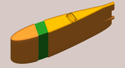
This D/B will have far less drag because of the elliptical shape AND the more exacting foil cross-section. BUT... the D/B drag is a small fraction of the total drag and the boat already will reach hull speed, so I don't expect more speed. I do hope, I will have better stall characteristics... it will stall at higher angles of attack and stall more gently than the stock D/B. IOWs it should be kinder, and be able to point better. Should being the operative word. I also chose the elliptical shape, because the biggest hinderance to ANYONE making the elliptical shape is building it. IT has always been its biggest drawback from early Snider cup planes... on. Mass war-time production of the Spitfire was slower than other planes because of the complexity. That all goes away in my case since the 3D computer aided design and 3D printer will make the cores within 3 decimal places accurate... trivial. Now to your question...

The short answer (Oops - already failed that one :) ) the tip vortices are far less with an elliptical tip than the squared-off tip. If you are willing to just take my word for it, you might want to skip the following blather.

The long version (since I would want to know why) - The tip vortices are caused by the pressure being higher on one side of the wing (D/B) than the other. The high pressure bleeds over to the low pressure side and swirls down stream causing lots of drag. Since the squared-off wing has a lot of area at the tip its has lots of pressure it wants to spill off to the low pressure side. It turns out through analysis and testing they found that the pressure on that squared-off wing effectively had an elliptical shape. So when they tested it by making the wing elliptical, they found it created just as much lift as the squared-off wing, even though it has less area. BUT as a benefit, it had less weight and less drag.

Vortices only occurs when lift is being created. If going DDW, there are no vortices. So the elliptical shape has no advantage except there is a little less skin drag. Which brings up another downside to my D/B design. If going DDW and I pull up the board, the big hole in the truck around that tip will create a lot of drag. I discount that as the boat seems to be faster just off the wind anyway and a little D/B is useful for that speed. That, you'll note by the lower rear bumper I've put into the design just above the ellipse.

Now the most common comparison of the two is WW2 Spitfire vs Mustang. https://www.airspacemag.com/flight-toda ... 180971225/ And depending on a person's bias one or the other is best. What articles like that fail to factor in is the purpose of those two planes. Like boats, there is no BEST. Just best at some aspect. The Spitfire was meant for defense of England. It had to climb very fast to altitude. It needed a lot of lift and had to have low drag. The Mustang was optimized for long distance cruise so it could reach deep inside of Germany. At cruise speed, very little lift is needed compared to the great speed so the vortices are small because the wing is going like our DDW boat. The added complexity of manufacturer was not justified in making it go faster or further.
Re: Strength how much stronger is the build than the original?
Strength is a sensitive subject. Too much strength is even more harmful than too little. In the D/B situation, if you make it too-strong and have a D/B strike, you break the boat hull. Which is better... having to replace a D/B or tow in and repair a sinking boat? I have chosen to match the skin's strength as best I can so if I get a strike the trailing edge continues to fail first as the stock unit. As far as bending of the D/B I have made it stronger. I used the number found by Roger's holding down the boat by the mast. I also added a safety factor. IOW, it should not break even with wind strong enough to knock-down the boat. The safety factor is to hopefully account for my lack of fiber glassing building ability. I am using Epoxy instead of Polyester.
Re: build time wouldn’t it be quicker to fix the old DB and use fairing epoxy to alter the foil? A template could be made to check the foil at various points for accuracy.
Oh hull Yeah! But I like projects as much as sailing. Before the boat had to be put-up, I did try to fix the D/B. However, trying to bond a structural member inside the other proved beyond my building ability. It broke off on the first sail. As it still sailed about the same with the shorter length, I'll clean up the stub bottom and have it as a backup in case the elliptical one breaks. :P

Also... this is an experiment and I have learned from my work. As someone pointed out above, IF I have to do another, I'll 3D print the molds and just layup the D/B like they build the originals.
Re: Hoisting what about using the cabin top winch? A rope clutch could be installed on that side for the jib sheets. (To free up the winch if needed)
Ix
I'm only putting as much metal/concrete ballast as needed to make it barely float. I don't have the number with me, but it seemed to be about 35 lbs. Even this I didn't want to lift all the time. I ain't getting younger. That is why I added the 2:1 block inside the D/B. That way I don't have any paraphernalia above deck. Over the years I've grown to hate wires behind furniture I can still see. I want to minimize all that clutter in my vision. Its a pet-peave.

That's why when I go to make my rear arch and new boom (later MX-n projects being designed) the main sheet tackle, boom-vang tackle, out-haul tackle, traveler tackle, one line reef tackle, will ALL be inside with only one line coming out in sight.

Re: Inqism-01: 3 Guesses. First 2 don't count.

Posted: Tue Jan 12, 2021 7:25 am
by Inquisitor
Finding a place to fiberglass and paint has been a challenge. What I've learned so far with this exercise:
  1. I'm not wild about fiberglassing.
  2. I procrastinate getting started, but its not so bad once I get into it.
  3. Fiberglass grinds and smooth's up easier than I dreaded. Although easier, I don't have the patients to get a mirror reflection.
  4. Using "slow" epoxy in a winter basement makes things take FOREVER!
  5. If I were to do a Daggerboard again, I'd make female molds... even for a one-off.
  6. I'd probably not do the Elliptical tip, that way I could make one mold and layup both sides.
  7. I've been designing a 40 foot cruising catamaran for years... No way in hull will I actually build it after this little trial.
I laid-up about 1/10" think worth of glass cloth. I then filled depressions using Bondo and then finished it off with a 4 oz layer of glass cloth to fill the course weave of the earlier ones and seal-in the Bondo.

Image

Image

Re: MX-1: 3 Guesses. First 2 don't count.

Posted: Tue Jan 12, 2021 8:09 am
by Ixneigh
Can’t wait for the performance assessment.it looks really nice! My suspicion is the square version will be better at the slower speed of these boats, relatively speaking.
Re fiberglass, it’s like any other skill. You’ll get better at it. The job appears nicely finished. Avoid bondo for anything but temp stuf though. You can make your own filler from the variety of things sold for such.
Re shorter dagger board: I hardly ever sail with mine all the way down. It knocks the speed quite a bit. If I mangled the bottom of mine by even a foot I’d just cut off the damage and fix it. I did however buy a 2nd board with boat purchase.
Re etc: the additional keel I added has made me stop thinking about board mods completely.

Ix