Here are my answers to those questions, although your usage/needs may be totally different:
Questions I have:
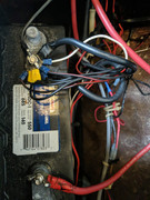
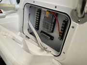
1. Which Bus bar should I use to make things neater
For the main panel, I stayed with the Macgregor Bolt wrapped in electrical tape. If it ain't broke... It doesn't meet any sort of yachting standards, but is very compact. For the secondary panel (see 2 below), and for the items wired directly to the battery like bilge pumps I used simple DC bus bars, mounted on a slice of HDPE that is bolted or epoxied in place, like this one:
https://www.amazon.ca/Distribution-BusB ... s9dHJ1ZQ==
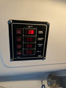
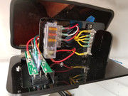
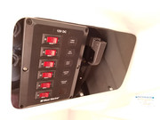
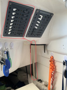
2. Do I need another DC Fuse Panel
Eventually, everyone needs another DC fuse panel (IMO). I started by replacing the original with a 6-fuse panel, then I added the original 4-fuse panel back in on the starboard side. Over time, the boat has become more and more comfortable with electrical gadgets, and waaay outgrown the original 4-gang panel.
3. Which DC adapter plugs Do I Need?
You can get 12V DC adapters from Amazon that work just fine, or any marine store. I have installed dedicated USB charging ports all over the boat, but be aware that most of them draw current when not in use, through little indicator lights. The best option I found is one with an integrated on/off switch like this one:
https://www.amazon.ca/gp/product/B07PZZ ... UTF8&psc=1
4. What wiring should I use so I won't need to redo it.
I use marine tinned wire in all cases, gauge appropriate to current. This stuff is strong, durable, and very well sheathed.
https://www.amazon.ca/Ancor-Marine-Grad ... 71&sr=8-12
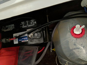
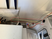
5. How hard to wire in a 50 watt solar and charge controller.
Piece of cake. With a single battery it becomes an independent system easily wired to the battery terminals. For a dual battery system it's a bit more complicated on how to make it charge both batteries. I chose to go with a Blue Seas ACR that automatically combines the batteries for charging when a charging voltage is sensed, and un-combines them when it senses that a battery is being discharged through load. I have two 50W solar panels mounted on the bimini top, Y-ed together with MC4 connectors and then connected to the wire heading to the charge controller with SAE automotive quick-connects. The wire runs down the backstay through the motor wiring boot into the bilge, and around to the solar controller and battery monitor that I have mounted under the galley, on the chine of the hull. Needs a little work to check, but real-estate to mount things is at a premium, and the system doesn't need to be checked often.